Electric vehicle ownership has moved past the early adopter stage into fleets, workplaces, apartment blocks and ordinary households, and the constraint has shifted with it. The bottleneck is no longer the vehicle but the charging point behind it, and most of those charging points must be retrofitted into buildings never designed to carry a dedicated high-current circuit. Pulling that circuit into a finished building is where projects quietly go wrong: walls reopened after decoration, driveways re-trenched, undersized conductors buried behind new plaster, and a service upgrade discovered only after the equipment has been delivered.
Remodeling EV charger installation means designing the charging point into the construction scope instead of adding it after handover. The work runs through five decisions taken in order: establish how much electrical capacity the building can genuinely spare, select the charging level and connector the vehicles on site need, fix the mounting position and cable route while surfaces are still open, secure permits and utility notification before equipment is ordered, and commission and document the circuit so it can be inspected and maintained. Handled in that sequence, a remodel absorbs the charger into costs that were already committed; handled afterwards, the same unit can cost several times more.
The sections below follow that sequence from the first capacity check to the final handover record.

Why a Remodel Is the Best Time to Plan EV Charger Installation
A remodel is the cheapest moment to install a charging point because the two largest cost lines, opening the building fabric and upgrading the electrical supply, are frequently already being paid for. Once walls are closed and surfaces finished, the same cable route can multiply the installed cost.
The market gives this timing decision urgency. According to the International Energy Agency, public charging points worldwide doubled in two years to pass five million by the end of 2024, and the European Union has begun mandating pre-cabling in new and renovated buildings specifically to avoid the future need to retrofit parking infrastructure, which the agency describes as costly (IEA Global EV Outlook 2025).
| Remodel phase | What to decide or install then | Cost if deferred |
| Design and permitting | Charging level, connector type, port count, panel capacity | Redesign, resubmission, new permit |
| First fix and civil works | Conduit, boxes, mounting backing, buried duct, isolator position | Surface trunking, core drilling, re-trenching |
| Electrical scope | Board ways, protective devices, service upgrade | Second mobilisation and a shutdown |
| Handover | Test records, labelling, circuit schedule, spare capacity notes | Repeat surveys and unknown capacity |
A remodel also forces a survey of the existing service, and that survey is when undersized panels, aged protective devices and missing capacity surface.

Assess Electrical Capacity Before You Start Remodeling
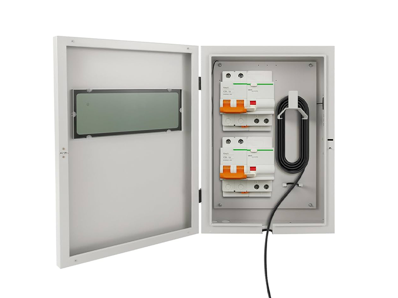
Before any equipment is selected, establish how much spare capacity the incoming supply and the distribution board can genuinely give to a continuous load. In most buildings this single check decides whether the project is a straightforward circuit addition or a service upgrade that must be engineered and permitted.
Reading Panel Capacity and Spare Service
Capacity is a measured quantity, not an assumption. A useful survey records the incoming service rating, voltage and phase arrangement, main device rating, busbar rating, usable spare ways, and an inventory of existing sustained loads such as heating, hot water, air conditioning, lifts and commercial kitchens.
Two details catch projects out. A unit described as a 240 V charger frequently sees 208 V in buildings fed from a three-phase supply, which cuts delivered power by roughly thirteen percent without changing the current the circuit must carry. And a spare way in the board is not the same as spare capacity, because a board can have empty ways while operating close to its rating.
The 125 Percent Continuous-Load Rule
Charging is classified as a continuous load, because the equipment draws its maximum rated current for three hours or more in a normal session. The branch circuit conductors and the overcurrent protective device must therefore be rated at no less than 125 percent of the maximum current the equipment will draw.
| Equipment rating | Minimum circuit rating at 125 percent | Typical copper conductor, 75 C terminations |
| 16 A | 20 A | 12 AWG |
| 24 A | 30 A | 10 AWG |
| 32 A | 40 A | 8 AWG |
| 40 A | 50 A | 8 AWG, or 6 AWG on long runs |
| 48 A | 60 A | 6 AWG |
Three further requirements follow. Each unit generally needs its own dedicated branch circuit unless an approved energy management system limits the combined draw, and receptacle-connected equipment is limited to 80 percent of the circuit rating, which is why high-power units are usually hardwired. Personnel ground fault protection is also required on charging receptacles, so a unit with built-in protection should not also sit behind a ground fault breaker, since stacking the two causes nuisance tripping.
When a Service Upgrade Becomes Unavoidable
An upgrade stops being optional when the board has no usable ways, when the main device or busbar rating is already reached, or when several chargers cannot be supplied at once. Four responses are available: upgrade the service, add an energy management system that caps combined draw, stagger charging by schedule, or reduce the equipment specification. The last three keep the decision with the project instead of the inspector.

Choose the Charging Level and Connector for the Project
Match the charging level to how long a vehicle actually sits parked rather than to how fast a charger sounds in a brochure. For most residential, workplace and destination remodels the correct answer is AC Level 2, while DC fast charging belongs on corridors, fleets and high-turnover sites and requires a three-phase supply and a substantially larger service.
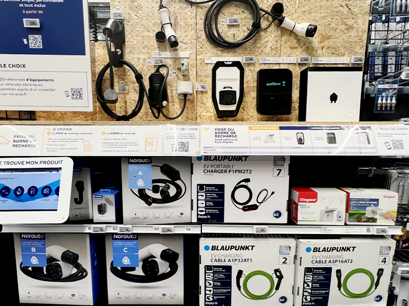
Comparing the available EV Charging Stations by format, mounting and power output is worth doing before the circuit is designed, because the equipment choice drives the electrical scope.
Level 1, Level 2 and DC Fast Charging Compared
| Level | Typical supply | Typical power | Typical full charge | Where it fits |
| Level 1 | 120 V AC, standard outlet | 1.4 to 1.9 kW | 30 to 50 hours | Low-mileage households, plug-in hybrids |
| Level 2 | 208 or 240 V AC single phase | 7 to 22 kW | 4 to 10 hours | Homes, workplaces, hotels, apartment residents |
| DC fast charging | 400 to 480 V three phase | 50 to 350 kW | 20 to 90 minutes | Highway corridors, high-turnover retail, fleets |
Dwell time is the decisive variable: a vehicle standing overnight needs a few kilowatts, not a few hundred. Specifying DC fast charging into an ordinary commercial remodel without a service study is the most common way a charging project becomes a substation project. Level 2 also carries better daily economics, because slower alternating current charging generates less battery heat than repeated high-power sessions.
Connector Standards That Must Match the Region
Connector compatibility is a regional decision, not a preference. On the alternating current side, Type 1, defined by SAE J1772, serves North America and Japan, while Type 2, defined by IEC 62196-2, serves Europe and much of the rest of the world, with the Chinese national standard used in mainland China. On the direct current side, the combined charging system exists in North American and European variants, China has a national standard of its own, an older Japanese connector persists on legacy vehicles, and the North American Charging Standard is the reference high-power connector for that region.
Two consequences matter on a remodel. A mixed or imported fleet needs either dual-standard equipment or an adapter strategy built into the specification, since changing connectors later means replacing cables or units. Connector decisions also belong in the handover documentation, because they determine what can be charged on the site years later.
Plan the Site Layout, Mounting and Cable Route
Decide the mounting position and cable route while the building is still open. The position must reach the vehicle charge port with a reasonable loop of slack, keep the connector clear of standing water and vehicle impact, and keep the run back to the distribution board as short and straight as the layout allows.
Mounting Height, Clearances and Weather Protection
| Item | Practical guideline |
| Indoor mounting height | Around 18 inches above finished floor as a baseline, subject to the equipment listing |
| Outdoor mounting height | Around 24 inches above finished floor, again subject to the listing |
| Working clearance | Room to open the enclosure, read the rating label and operate the isolator |
| Enclosure rating | Weatherproof for wet locations, higher where fully exposed |
| Vehicle protection | Bollards or a protective post wherever a vehicle can strike the unit |
| Connector stowage | A holster within reach of the charge port, plus cable management for long cords |
The equipment listing overrides rules of thumb, and the position should be checked against the vehicle rather than the plan. A unit mounted behind a parked car, or one whose cable cannot reach the charge port without crossing a walkway, will be used badly and damaged early. Drainage matters as much as protection rating, because standing water, snow accumulation and roof runoff degrade connectors regardless of enclosure rating.
Routing, Containment and Trenching During Construction
Rank routing options by cost before opening any surface.
- Along an existing internal service route in a plant room or riser using tray or trunking, normally the cheapest option and the easiest to extend.
- In conduit buried within a wall or slab before lining or pouring.
- In surface-mounted trunking, which avoids demolition but is visually intrusive and slower to install.
- Through a buried duct to a detached garage or remote bay, requiring correct burial depth, mechanical protection, a draw rope and accessible inspection points.
Two coordination points are easy to forget. Smart equipment needs connectivity, so structured cabling or confirmed cellular coverage belongs with the electrical route rather than after commissioning. And the route should be photographed and recorded before the surface closes, noting conductor size, circuit reference and protection device.
Permits, Approvals and Utility Notification
Charging equipment is electrical installation work, so it normally requires an electrical permit and a final inspection before the circuit is energised. If the added load may affect the service, metering or transformer, the utility must be notified, and for larger loads that notification is a prerequisite rather than a formality.
Official programmes treat these as ordered gates, which is why the Joint Office site selection checklist places utility engagement and code review ahead of construction.
- Confirm the applicable code edition and local amendments with the authority having jurisdiction, since an older adopted edition applies different protection and load rules.
- Agree in advance who submits drawings, obtains approval, arranges inspection and closes out records.
- Notify the network operator or utility of the added load and confirm metering, tariff and connection works required before energisation.
- Apply for planning consent where the unit, pedestal or bollards are visible external additions, or the site is protected.
- Obtain written consent covering position, cable route, wayleave and maintenance access where the site is leased, shared or multi-tenant.
- Confirm the equipment carries the required listing and that certification documents are available for the inspector.
- Close out with an installation certificate, test results, a labelled circuit schedule and the equipment documentation.
Deferring these steps carries costs that appear much later. Unpermitted electrical work can be excluded from insurance cover if it contributes to a loss, is disclosed in a property transaction, and may be ordered removed by a building official.
The Step by Step Remodel Installation Sequence
Sequence the work so concealed installation happens before finishes and energised work happens after inspection. Three stages keep the electrical scope, the construction programme and the inspection milestones aligned.
The right installation tools and containment hardware are specified at the first stage, because retrofitting them into a closed wall defines unplanned cost.
Stage One, Rough-In Before Walls Close
The circuit is designed and fixed, then conduit, boxes, mounting backing and the isolator position go in before the wall is lined or the slab poured. Conductors are pulled with a service loop left at both ends so the unit can be positioned without splicing, and the route is photographed before the surface closes. Where the parking position is remote, the buried duct is laid and proved with a draw rope now.
Stage Two, Mounting and Electrical Connection
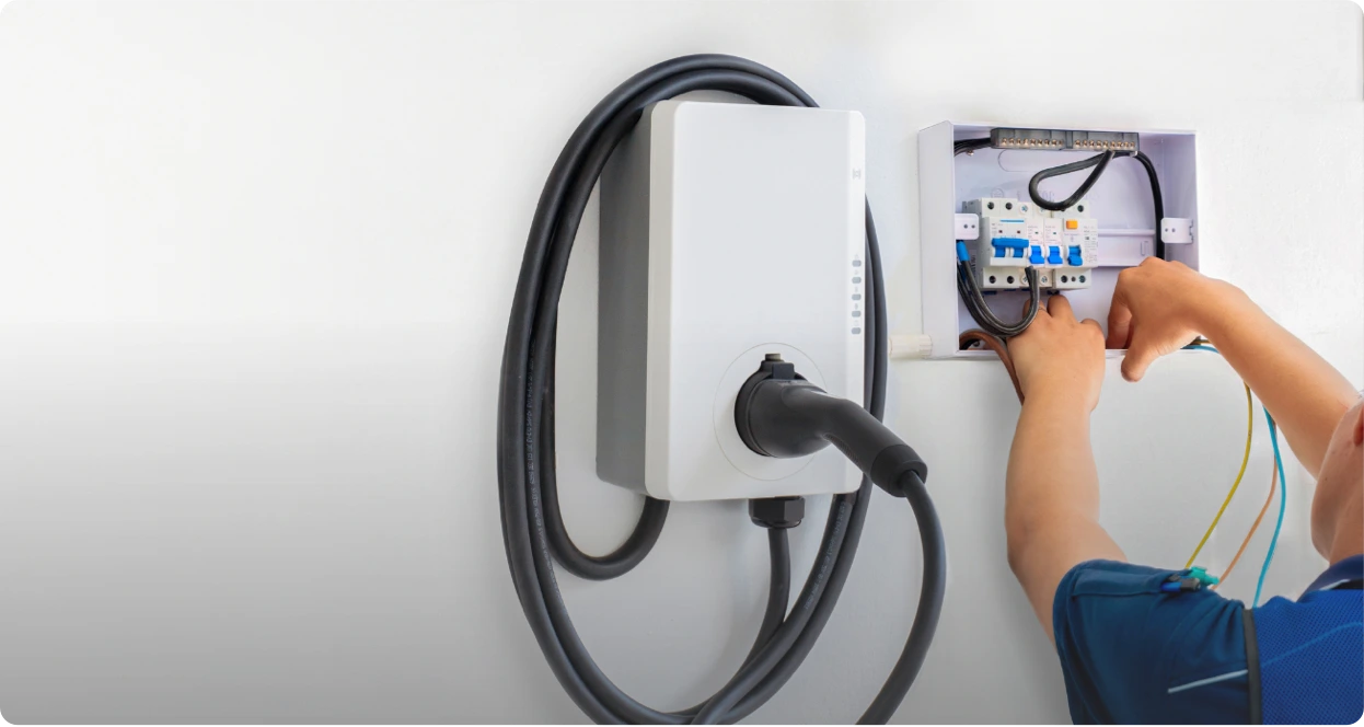
The unit is mounted level on the prepared backing, with terminations torqued to the manufacturer’s figure rather than to feel. Line, neutral where required and the equipment grounding conductor are connected, and data cabling is kept separated from power conductors. The protective device is fitted, the circuit labelled, and the conductor size recorded; where the unit already provides built-in ground fault protection, a standard breaker is used instead. The circuit is then energised, and polarity, voltage and phase rotation are verified before any session is attempted.
Stage Three, Commissioning, Testing and Handover
Testing is a defined sequence rather than a plug-in check.
- Visual inspection for damaged components, loose terminations, exposed conductors and sealed enclosures.
- Insulation resistance measurement on the new circuit.
- Earth continuity and protective conductor verification.
- Trip test of the residual current device at its rated residual current.
- Voltage and voltage drop check with the circuit under load.
- Live charging session confirming communication with the vehicle, expected current and clean termination.
- Handover pack: test certificates, circuit schedule, labelling, operating instructions, warranty terms and maintenance interval.
Recording the spare capacity, conductor size and spare ways available turns the next charger addition into a minor variation rather than a fresh survey.
Doing It Yourself or Hiring a Qualified Installer
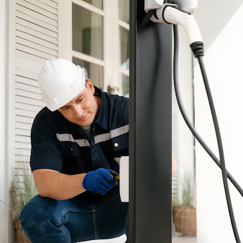
A competent electrician can physically connect a charging point, but the work is normally only compliant and certifiable when designed and signed off by someone holding both a general electrical qualification and specific training in electric vehicle charging, plus registration under an approved competent person scheme where the market relies on self-certification.
A specialist Installer Operator model also absorbs inspection and network notification into the job, which ad-hoc labour rarely does.
What a Qualified Installer Must Hold
- A current qualification covering the wiring regulations in force, including the sections addressing charging installations specifically.
- Recognised training covering circuit design, load calculation, earthing arrangements and protective device selection.
- Registration under an approved competent person scheme where self-certification replaces a separate building control application.
- Network operator registration or notification capability where the added load affects the service.
- For publicly funded work, recognised charging-specific certification, which United States federal requirements impose on electricians installing or maintaining charging equipment.
A general electrician without charging-specific training can still connect a unit, but the work usually cannot be self-certified, which means a separate inspection, an additional fee, and no installation certificate to hand to a buyer, an insurer or a future maintenance contractor.
Can You Install an EV Charger Yourself
Three risks decide the answer. The regulatory risk is that uncertified work is often unlawful in itself, regardless of whether it is safe. The insurance risk is that a policy may exclude damage arising from unpermitted electrical work, turning a circuit fault into an uninsured loss. The warranty risk is that most manufacturers void the equipment warranty when the unit is not installed by a registered installer.
The physical risk sits underneath all three. Charging circuits run at high current for hours in damp garages and exposed parking positions, so incorrect earthing or a badly selected protective device creates a genuine shock and fire hazard. An owner can legitimately choose the equipment, prepare the route, arrange access and manage documentation, but circuit design, the electrical connection and certification belong with a qualified installer.
Applying the 80/20 Rule to Charging Design
In installation terms the 80/20 rule is the limit on a continuous load and is the counterpart of the 125 percent rule: charging must not exceed 80 percent of the branch circuit rating, so a 40 amp circuit carries a 32 amp load. The same shorthand also describes battery practice, where daily charging is kept between 20 and 80 percent of capacity.
The Electrical 80 Percent Rule
The two expressions describe the same arithmetic from opposite directions. A 32 amp unit on a 40 amp circuit draws 80 percent of the circuit rating, and that circuit is rated at 125 percent of the unit.
| Equipment rating | Circuit rating at 125 percent | 80 percent of circuit rating |
| 16 A | 20 A | 16 A |
| 32 A | 40 A | 32 A |
| 40 A | 50 A | 40 A |
| 48 A | 60 A | 48 A |
The consequences are direct. A 48 amp unit cannot be protected by a 50 amp breaker, even though 48 is less than 50. Where spare capacity supports only a 40 amp circuit, the specification should be a 32 amp unit, and the difference is not a small performance penalty but persistent nuisance tripping. Applied early, the rule more often changes the equipment list than the civil scope, which is the cheaper outcome.
The Battery 20 to 80 Percent Habit
Lithium-ion cells experience the least stress in the middle of their state-of-charge range, while sustained deep discharge and prolonged time at high charge both accelerate capacity loss, and repeated high-power charging adds heat that compounds the effect.
For a remodel, that habit translates into specification rather than advice. A programmable charge limit caps sessions automatically, scheduling moves charging into off-peak tariff windows without hardware change, and load balancing spreads available capacity across multiple points. One documented exception applies: certain lithium iron phosphate batteries are designed to be charged to full periodically so the battery management system can recalibrate, and the vehicle manual should be followed.
Cost Drivers, Timeline and Mistakes to Avoid
The equipment is rarely the largest line in the budget. The dominant costs are the cable route, the state of the existing electrical service, the civil work needed to reach the parking position, and the approvals process.
Public guidance from the U.S. Department of Energy treats site assessment, power requirements and cost estimation as one connected design exercise completed before equipment is ordered.
What Actually Drives the Cost
| Cost item | Why it varies | How a remodel reduces it |
| Equipment | Power rating, connector configuration, network features | Order after level and connector are fixed |
| Circuit and distribution | Distance to the board, conductor size, spare ways | Install circuits while walls are open |
| Cable route and civil work | Penetrations, containment, trenching, reinstatement | Combine with other groundworks and interior works |
| Service upgrade | Existing capacity, panel age, utility connection | Bundle with the main electrical scope |
| Approvals and inspection | Local amendments, planning consent, utility process | Submit with the main building application |
| Commissioning and training | Number of units, network setup, familiarisation | Complete in the same mobilisation |
| Operation and maintenance | Uptime expectations, spares, periodic testing | Specify test equipment and spares at handover |
Timelines vary with scope rather than with the charger. A single visit is realistic where the service has spare capacity, the route is short and the mounting surface is prepared; time is added by a service upgrade, an obstructed route, trenching, foundation work, utility coordination and inspection scheduling.
Five Mistakes That Break a Remodel Installation
- Ordering a 48 amp unit for a 50 amp circuit, then living with recurring breaker trips.
- Closing walls before conduit, backing and the isolator position are installed, which forces surface trunking and often a longer run with a larger conductor.
- Fitting a ground fault breaker on a circuit whose equipment already provides built-in protection, causing nuisance tripping without adding safety.
- Sizing the service and board for one charger while ignoring the second and third units that arrive within a couple of years.
- Energising the circuit before inspection, which can require finished work to be opened up again and delays the certificate the site needs for insurance and records.
These failures recur often enough to be catalogued as a distinct problem set, and the 5 EV Charging Station Installation Mistakes that appear most frequently are worth checking against a design before equipment is ordered.

Frequently Asked Questions
These three questions normally surface after the main decisions are taken, and each one changes the equipment list or the metering arrangement rather than the installation sequence.
Can an EV charger be installed when the parking space is detached from the building?
Yes, provided the route is engineered rather than improvised. A remote bay or detached garage is normally served by a buried duct at appropriate depth with mechanical protection and accessible inspection points, a conductor sized for the full run and checked for voltage drop, a local isolator within the required distance of the equipment, and outdoor-rated equipment with a protective post. Underground work and reinstatement dominate the cost, so the pedestal position should be fixed at design stage rather than during construction.
Do I need a separate electricity meter for an EV charger?
Not usually for a single residential or small commercial unit, because the charger can be supplied from the existing service on its own circuit. A separate meter or submeter becomes useful where consumed electricity must be recharged to tenants, employees or customers, where a dedicated time-of-use or charging tariff applies and consumption should be reported separately, or where an operator needs usage data for reporting. Metering rules differ between markets, so the arrangement should be confirmed with the supplier before the service design is finalised.
Can a charger be added later without opening finished walls?
It is possible but consistently more expensive. Surface trunking, an external route along the facade, or a longer buried run can all avoid demolition, and a pedestal can move equipment away from the building fabric entirely. The penalties are a longer run with a larger conductor, a visible route that may require consent in a protected area, and a greater risk of voltage drop. Including conduit, backing and spare board capacity during the remodel costs a small fraction of that later work.