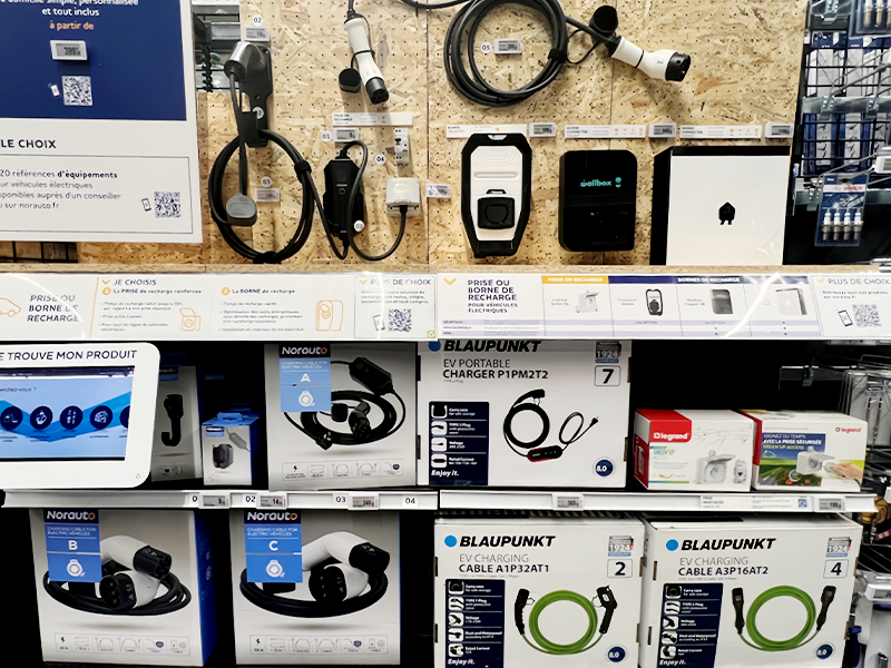
Plugging a connector into an electric vehicle looks purely mechanical, yet the moment the plug is seated an invisible conversation begins. Before any energy moves, EV charging stations and the vehicle confirm the connection, verify grounding, read the cable’s rating and agree on how much power the battery can safely accept. That exchange decides whether a session finishes in twenty minutes or fails at the curb with an error.
A charging station and a car communicate in three layers. The first is a low-level electrical handshake over the Control Pilot and Proximity Pilot pins of the connector. The second is a high-level digital exchange that travels over the same cable using Power Line Communication or Controller Area Network. The third is a network layer that links the station to a central management system through protocols such as the Open Charge Point Protocol.
Following that conversation from the plug backwards explains how charging behaves and what to check when it stops.
Why EV Charging Stations and Cars Need to Talk
Communication exists because neither side can judge safety alone. The vehicle knows its battery voltage, temperature and state of charge, while the equipment knows the cable rating, the available supply and the condition of the installation. Only by exchanging these facts can the two choose a current that is safe for the cable, acceptable to the battery and sustainable for the supply.
Modern EV charging stations serve a wide mix of vehicle models on the same hardware, and the rate a driver sees is the lowest ceiling imposed by three parties: the vehicle’s battery and onboard charger, the charging equipment and its cable, and the electrical supply feeding the site. Communication is the process of discovering that number and holding the session inside it.
The Physical Handshake at the Connector
The handshake is a set of low-voltage signals exchanged through dedicated pins, defined for AC charging by IEC 61851 and the SAE J1772 scheme. The Control Pilot line carries a voltage and a pulse-width modulated waveform that the vehicle reads, while the Proximity Pilot line reports the current the attached cable can carry. Power transfer is blocked until both sides agree the connection is valid.
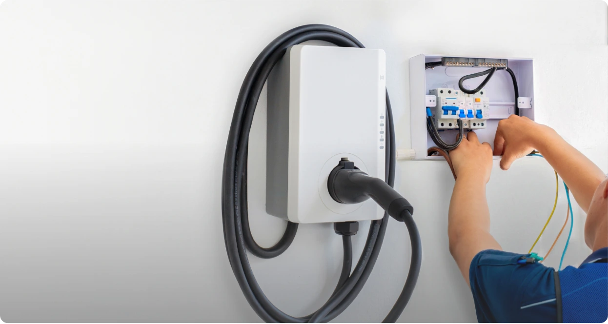
Connector hardware, wiring and pilot circuits sit inside the charging station components of a unit, so a bent pin or a degraded pilot wire can prevent a session before any high-power electronics are involved.
Control Pilot: The Main Conversation Line
The Control Pilot pin carries a nominal 1 kHz square wave that the station generates and the vehicle modifies by changing its internal impedance. The voltage reports the session state, and it steps down through a defined sequence that ends only when charging is permitted. The complete signalling definition and the four charging modes are set out in IEC 61851, the international reference for conductive charging.
| Control Pilot voltage | Session state |
| Plus or minus 12 V | No vehicle connected |
| 9 V | Vehicle detected, not ready |
| 6 V | Ready to charge |
| 3 V | Charging, ventilation required |
| 0 V | No power available |
| Minus 12 V | Fault |
Proximity Pilot and Current Signalling
The Proximity Pilot pin forms a resistive circuit to protective earth, and its resistance identifies the cable’s maximum rating, so an undersized cable cannot be pushed past its design limit. Common values run from 1500 ohms for a 13 A cable down to 100 ohms for a 63 A cable. The same circuit confirms the connector is fully latched, after which the duty cycle of the Control Pilot waveform advertises available current without any digital connection.
| Duty cycle | Maximum current signalled |
| 10 percent | 6 A |
| 25 percent | 15 A |
| 50 percent | 30 A |
| 80 percent | 48 A |
| 85 percent | 51 A |
| 90 percent and above | Reserved for digital, up to 80 A |

How AC and DC Charging Communicate Differently
The two systems differ because the equipment that converts power sits in different places. In AC charging the vehicle’s onboard charger performs the conversion, so the station only advertises an available current and the car keeps control. In DC fast charging the station converts the power, so the vehicle must continuously send voltage and current requests that the equipment follows.
Level 2 AC Charging Communication
A Level 2 connection can run on the analogue handshake alone. The station signals a maximum current, the onboard charger converts the supply, and the battery management system limits what the pack accepts. Features such as scheduled charging and authentication are optional additions, which is why basic AC charging remains the most interoperable form in use.
DC Fast Charging Communication
In a DC charging station, the equipment rectifies the grid supply internally and delivers controlled direct current to the battery, which places the charger inside the charging loop and makes continuous communication mandatory. After the handshake, the two sides establish a digital link and run a sequence covering insulation testing, connector locking, pre-charging the DC bus and power transfer. The vehicle sends target values and can revise them at any moment.
The Digital Protocols Behind the Session
High-level communication carries digital data over the charging cable itself, so no extra wiring is needed. The dominant technologies are Power Line Communication, used mainly by the Combined Charging System, and Controller Area Network, used by several DC charging standards, supported by Signal Level Attenuation Characterization to keep the signals clean.
Power Line Communication
Power Line Communication superimposes a high-frequency data signal on the conductors that carry power, using a physical layer derived from HomePlug Green PHY and a full internet protocol stack above it. Because it supports ordinary networking over the cable, it enables vehicle identification, secure payment, firmware updates and the services defined by ISO 15118.
Controller Area Network and Signal Isolation
Controller Area Network is a robust, real-time serial bus originally developed for in-vehicle electronics and later adapted for DC charging control. It carries short, deterministic messages with strong error detection, which suits the tight timing of high-power charging. Where several charging points operate side by side, Signal Level Attenuation Characterization measures the channel and selects the carrier frequency with the best signal-to-noise ratio, keeping each session isolated from its neighbours.

Standards That Keep EV Charging Stations Compatible
Standards let a vehicle from one manufacturer charge on equipment from another. The core documents are IEC 61851 for the charging system and its signalling, ISO 15118 for high-level smart charging and Plug and Charge, the SAE J1772 and SAE J3400 connector specifications for North America, DIN 70121 for early Combined Charging System DC charging, and the GB/T series for the Chinese market.
| Standard | Scope |
| IEC 61851 | Charging system, charging modes and Control Pilot signalling |
| IEC 62196 | Connector and inlet types including Type 1, Type 2 and CCS |
| ISO 15118 | High-level communication, Plug and Charge and vehicle-to-grid |
| SAE J1772 | North American AC connector and pilot signals |
| SAE J3400 | North American Charging Standard connector |
| DIN 70121 | Digital communication for early CCS DC charging |
| GB/T 20234 | Chinese connector standard and DC communication |
| IEC 63584 | Open Charge Point Protocol as an international standard |
Connector shapes and communication capabilities are related but not identical. Two connectors may look alike while supporting different protocol versions, a frequent source of confusion when imported vehicles meet unfamiliar infrastructure.
How an EV Decides How Much Power to Accept
The vehicle, not the station, governs how much power enters the battery. The battery management system measures cell voltage, temperature and state of charge, then sends a request that the station follows. The station’s rating is only an upper bound, so a vehicle on a very powerful charger still draws only what its own limits permit.
The Role of the Battery Management System
The battery management system tracks individual cell voltages, pack temperature, state of charge and degradation, and converts that picture into a safe operating window. During DC charging it issues continuous requests and can reduce or halt the session if a measurement leaves the window. This is why two vehicles on identical chargers can charge at very different rates.
Charging Rate Tapering
Charging power is deliberately reduced as the battery fills. At a low state of charge the pack absorbs energy quickly, but as it approaches full the management system lowers the current to protect the cells and manage heat. Cold or hot conditions restrict power further until the pack reaches a suitable temperature.

How EV Charging Stations Connect to the Internet and Backend
Stations reach the internet through wired and wireless links, then use standard protocols to talk to a central platform. Ethernet and RS-485 serve local systems, Wi-Fi, cellular and Bluetooth connect the station outward, and the Open Charge Point Protocol carries status, metering and control messages to the backend.
Wired and Wireless Connections
Ethernet provides high bandwidth between a station and an on-site platform, which suits sites that upload substantial data or control many chargers. RS-485 is a lower-cost, noise-tolerant bus often used between a station and local devices such as energy meters. Wi-Fi suits home and light commercial sites with an existing network, cellular keeps remote and highway units online, and Bluetooth handles short-range tasks such as commissioning a new unit or starting a session from a phone without any internet connection.
Open Charge Point Protocol
The Open Charge Point Protocol is an application-layer standard maintained by the Open Charge Alliance and published as IEC 63584, with versions 1.6 and 2.x in wide use. It carries status reports, meter values, error notifications and remote commands between station and backend, which makes app-based monitoring, remote diagnostics, firmware updates and smart charging schedules possible. Because it is vendor-neutral, an operator can mix equipment from different suppliers inside one network.
Roaming and Plug and Charge
Roaming protocols such as OCPI, OCHP, OICP and eMIP align separate operators into something that behaves like one system, handling identification, tariffs, session start and settlement between parties. Plug and Charge goes further: where the vehicle and the network both support the relevant ISO 15118 capabilities, the car presents cryptographic credentials over the cable and the session begins and bills automatically.
What Happens When Communication Fails
When the handshake or the digital link fails, charging either never starts or stops partway through. The fault can sit in the connector, the cable, the vehicle, the station firmware or the network connection, and the symptom is often identical regardless of cause, so troubleshooting works best as a process of elimination.
Common Communication Faults
| Symptom | Likely cause |
| No charging after plugging in | Poor pin contact, damaged pilot circuit, station not authorised |
| Charging starts then stops | Digital link dropout, insulation fault, overheating |
| Power below the expected rate | Duty cycle limit, cable rating, conservative battery request |
| Error shown immediately | Ground fault, communication timeout, incompatible standard |
| Station invisible in an app | Network link down or backend outage |
First Steps to Troubleshoot
- Disconnect and reconnect the connector, checking that it latches cleanly.
- Inspect the connector and cable for moisture, debris, bent pins or damage.
- Try another charging point to see whether the problem follows the vehicle or the station.
- Confirm that the vehicle and the station share a common standard and connector type.
- If an app cannot see the station, test another payment method to separate a network fault from a hardware fault.
- Report persistent faults with the exact error message, which often identifies the failing layer.
Well-made charging cable assemblies and undamaged connectors eliminate a large share of these faults before they occur.
Safe Charging Do’s and Don’ts
Safe charging means respecting the limits the communication system is designed to enforce. Use compatible equipment, keep connectors clean and undamaged, let the vehicle manage the rate, and treat every error message as meaningful rather than a nuisance to be ignored.
What to Do
- Charge with equipment rated for the vehicle and the on-site supply.
- Keep the connector inlet and the plug clean, dry and free of debris.
- Let the battery management system control the charging rate.
- Stop and inspect the hardware if an error appears more than once.
- Schedule maintenance so pilot circuits, insulation and connectors stay within specification.
What to Avoid
- Do not force a connector or adapter that does not seat smoothly.
- Do not ignore repeated communication or ground-fault errors.
- Do not leave damaged cables in service.
- Do not expect a charger’s advertised rating to reach every vehicle.
- Do not assume a compatible connector guarantees a compatible protocol.

Frequently Asked Questions
These answers extend the layers above, covering everyday charging habits, offline operation and weather effects.
Should I charge my EV to 100% every night?
For most owners of lithium-ion vehicles, charging to 100 percent every night is unnecessary and slightly accelerates degradation. Routine charging is usually capped between 70 and 90 percent, because cells held at a high state of charge age faster. Reserve a full charge for the day before a long trip.
Does a charging station need an internet connection to deliver power?
No. Basic power delivery depends only on the local handshake and the station’s own electronics, so charging continues during a network outage. An internet connection is required for authentication, remote payment, roaming and app-based monitoring, so a station that is offline may still charge but may fall back to a simpler access mode.
Why does charging power drop in cold weather?
Cold cells accept charge more slowly, so the battery management system reduces the requested current until the pack warms up. Preconditioning the battery before a fast-charging stop restores much of the lost rate. When the pack is already warm from driving, the effect is small.