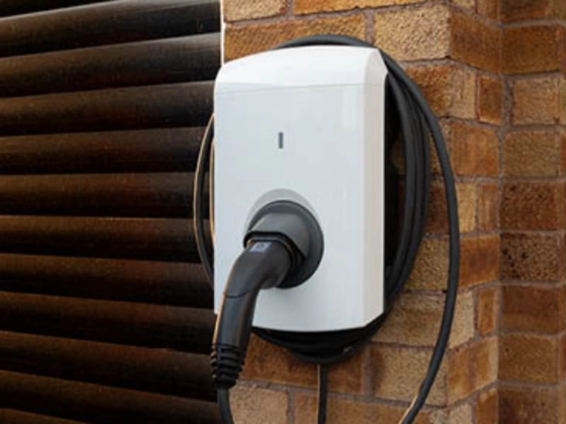
The sudden explosion of electric vehicles on the road has turned what used to be a niche electrical job into a daily necessity: maintaining the charging infrastructure. It isn’t just about plugging a car in and seeing if the lights turn green. Ensuring that a high-voltage Electric Vehicle Supply Equipment (EVSE) unit is actually safe for the public requires more than a standard multimeter. This is where an EV Charger Test Kit comes into play, acting as a “dummy” vehicle to simulate various charging states and faults without risking an actual Tesla or Ford F-150.
Why Testing Infrastructure is Non-Negotiable
There is a certain level of unpredictability when dealing with outdoor electrical hardware. Rain, temperature fluctuations, and physical wear can degrade the internal components of a charging station. Using an EV Charger Test Kit allows technicians to verify that the safety interlocks—the things that prevent a live current from flowing until a secure connection is made—are functioning exactly as intended. It’s about peace of mind, really. Nobody wants to be responsible for a station that delivers a surge or fails to ground properly during a storm.
Core Components of an EV Charger Test Kit
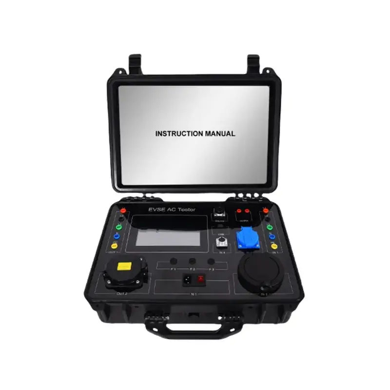
Before diving into the “how-to,” it helps to understand what is actually inside that rugged plastic carrying case. Most kits aren’t just one tool but a suite of adapters and simulators.
- The Simulator Block: The heart of the EV Charger Test Kit, which mimics the communication protocol of an EV.
- Type 1/Type 2 Adapters: Depending on the region, these allow the kit to interface with different plug standards.
- CP (Control Pilot) Signal Terminals: These allow an oscilloscope or multimeter to “read” the communication between the charger and the vehicle.
Fault Simulation Switches: Buttons that manually trigger an Earth Fault or a CP Error to see if the station shuts down.
Step-by-Step: How to Perform Charging Station Testing
Performing these tests requires a methodical approach. It’s easy to get distracted by the digital readouts, but the sequence matters immensely for accurate diagnostics.
1. Visual Inspection and Physical Connection
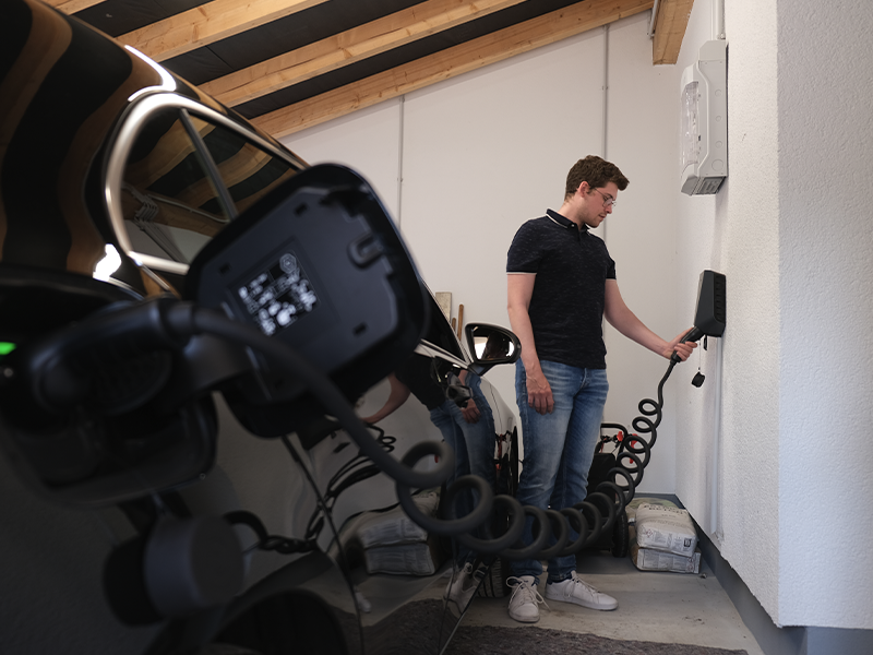
First things first, check the cable for cracks. Once the physical integrity is confirmed, connect the EV Charger Test Kit to the charging station’s nozzle. At this stage, the station should recognize a “Plugged In” state (State B) but should not yet be delivering power.
2. Simulating Vehicle States
Most kits feature a rotary switch that cycles through different vehicle states. This is perhaps the most critical part of the process.
- State A: Disconnected (Power off).
- State B: Connected, but vehicle not ready to charge (Power off).
- State C: Vehicle ready and charging (Power on/Ventilation not required).
- State D: Vehicle ready and charging (Power on/Ventilation required).
If the station starts humming or shows a “Charging” light while the kit is still in State A, there is a serious logic board failure that needs immediate attention.
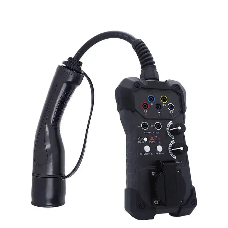
3. The PE (Proving Earth) Pre-Test
Before running high current, use the kit’s PE Pre-Test function. This checks if there’s any dangerous voltage on the Earth terminal. It’s a quick touch-sensor test on many modern EV Charger Test Kit models, but skipping it is a gamble that just isn’t worth taking.
4. GFCI and Error Testing
Finally, you want to break things—on purpose. Use the kit to simulate a Ground Fault. The station’s circuit breaker or internal GFCI should trip almost instantly. If it doesn’t, the station is a safety hazard.
Technical Specifications Comparison
When selecting or using an EV Charger Test Kit, the specifications often vary based on whether you are testing a residential AC “Level 2” charger or a commercial DC fast charger.
Feature | AC Test Kit (Level 1/2) | DC Fast Charge Test Kit |
Voltage Range | Up to 250V (Single Phase) | Up to 1000V+ |
Communication | PWM (Pulse Width Modulation) | PLC (Power Line Communication) |
Primary Goal | Safety & Interlock Verification | Protocol & High-Speed Handshake |
Portability | Handheld/Small Case | Large, often wheeled units |
Common Issues Discovered During Testing
It is quite common to find “ghost” errors that only appear under load. Sometimes, a station works fine for five minutes and then shuts down. Using the EV Charger Test Kit to monitor the CP signal over a longer duration can reveal fluctuations in the duty cycle, which indicates how much current the station is telling the “car” it can handle.
Frequent “Fail” Points:
- Loose Wiring: Often found in newly installed residential units.
- Signal Noise: Interference that disrupts the handshake between the charger and the kit.
- Worn Contactors: The physical switch inside the charger that clicks when charging starts; these eventually wear out.
Final Observations on Maintenance
Testing isn’t a “one and done” scenario. With the sheer amount of usage public chargers get, an annual or bi-annual checkup with an EV Charger Test Kit is becoming the industry standard. It’s a bit like an oil change for the electric age—unseen, slightly tedious, but absolutely vital for the longevity of the infrastructure.
When the testing is complete, always ensure that the station resets correctly and that no error codes remain on the display. A clean bill of health means the next driver who pulls up at 2 AM in the rain won’t be left stranded with a “Fault” light and a dead battery.
For more informatio about the EV Charger Test Kit, you can check our guide: EV Charger Test Kit: What’s Inside and What Can It Test?